components mounted on flex PCBs
When it comes to designing electronic devices, there are a number of considerations that must be made before deciding whether or not a flex PCB is the right choice. These considerations include the complexity of the design, the materials and assembly process used, and the environmental factors that may affect performance or reliability. Flex PCBs also offer unique advantages that can help simplify the design and assembly process, including a smaller form factor and improved thermal management.
The most common method of mounting components on a flex circuit is surface-mount technology (SMT). This involves placing the parts onto the board with a specialized automated system, which then solders them into place using a wave solder machine. Alternatively, through-hole technology (THT) can be used for larger or bulkier components that cannot be mounted by SMT. Both methods require careful attention to detail and adherence to industry standards, in order to ensure that the resulting assembly is accurate and reliable.
To prevent stress and failure, traces on a flex pcb should always be routed perpendicular to the bend axis of the board. This will eliminate stress points and ensure that the traces do not break during bending or folding of the pcb. In addition, it is important to avoid abrupt changes between wide and narrow traces to minimize the risk of stresses that may lead to failures or shorts. To reduce this risk, the traces should be connected using fillets or a gradual transition. It is also recommended to use circular sections in the flex areas of the board with large radiuses to reduce tearing.
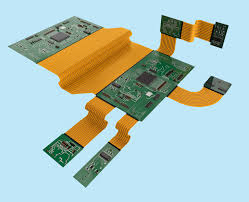
How are components mounted on flex PCBs?
The copper conductors on a flex pcb should be insulated with either an epoxy or polyimide film. This helps protect the copper from corrosion and provides a surface that is easy to solder. The insulator layer must be thick enough to meet the necessary mechanical requirements of the flex circuit.
In addition, the insulator must have a smooth surface finish to make it easy for components to adhere to the bare copper. The most popular PCB surface finish is Electroless Nickel Immersion Gold (ENIG), which is used on about 80% of all PCBs. However, there are a number of other finishes that can be used to improve etch yield or the material strength of the flex circuit.
Stiffeners are also often utilized to stiffen flex circuits, particularly for dynamic applications that are subjected to repeated bending. These are typically made from FR4 or Kapton and attached to the flex circuit with acrylic thermally-cured adhesives. These stiffeners can provide additional support for the flex circuit and can help in weight balance, strain reduction, and heat dissipation.
In addition to the above factors, a flex circuit must be designed to handle a variety of electrical and mechanical stresses, including thermal cycling and the effects of external environmental factors such as humidity or chemical exposure. This can require a significant amount of engineering effort to be done correctly, but it is essential for the success of the final product.